
In modern industrial automation, simply detecting an obstacle is often not enough. For AGVs, mobile robots, automated production equipment, and industrial machinery, the real challenge is determining where detection should occur, how the detection area should change with operating conditions, and how the sensor should communicate the detection result to the control system.
This is where a Safety Area Scanner can provide significant value. By defining specific detection zones around equipment, manufacturers and system integrators can create more structured protection strategies while maintaining the flexibility required by industrial applications.
However, designing an effective protective zone is not simply a matter of drawing a virtual rectangle around a machine. Detection distance, scanning angle, object characteristics, machine movement, environmental conditions, response requirements, and control-system integration all need to be considered.
This article explains how to approach Safety Area Scanner protective-zone design and configuration from an industrial B2B perspective.
1. What Is a Safety Area Scanner?
A Safety Area Scanner is generally used to monitor a defined area and determine whether an object or person has entered that area.
In industrial applications, area scanning technology can be used for:
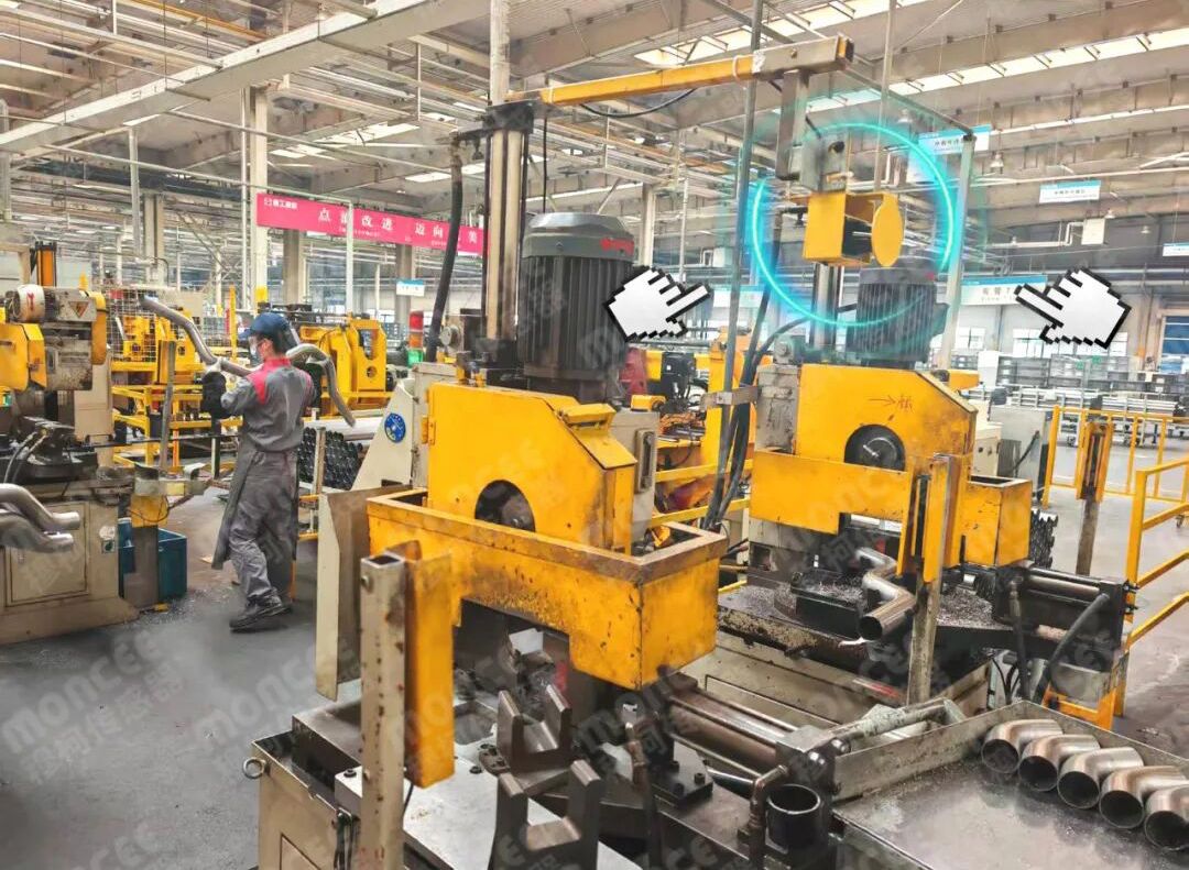
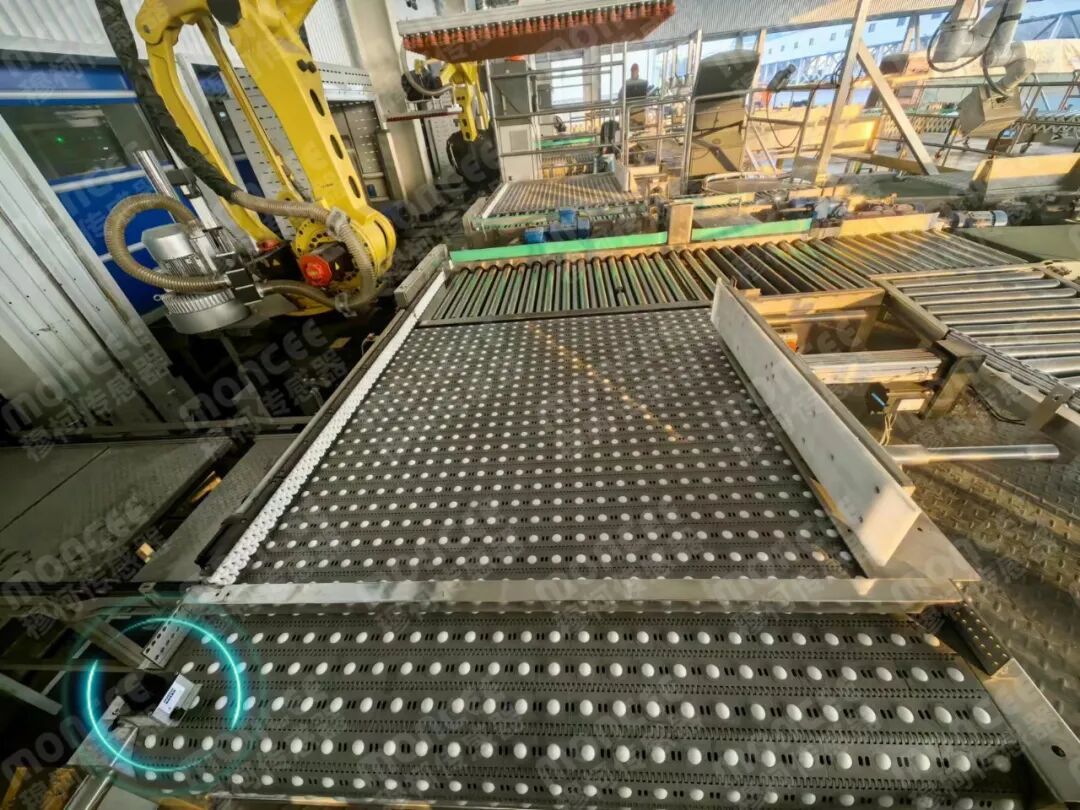
AGV and AMR obstacle detection
Mobile robot area monitoring
Automated equipment protection
Robot working-area monitoring
Personnel detection
Collision prevention
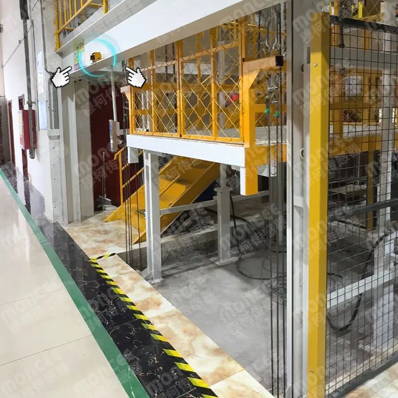
Restricted-area monitoring
Industrial logistics systems
It is important, however, to distinguish between an industrial laser scanning sensor with area-detection functions and a formally certified safety laser scanner.
The MILS-F30 documentation identifies the product as an industrial laser scanning sensor for navigation and obstacle avoidance, capable of area detection and protection. It uses TOF ranging technology and provides a 270° field of view with a maximum detection distance of 50 m.
Therefore, when specifying a product for a formal machine-safety application, buyers should independently verify the applicable safety certification and standards rather than assuming that every product marketed as a LiDAR or area scanner is a certified Safety Laser Scanner.
2. Start With the Application, Not the Sensor
A common mistake in industrial projects is selecting the scanner first and designing the detection area afterward.
A better approach is to define the application requirements first.
Before configuring a protective zone, determine:
What needs to be detected?
Where can the target enter the monitored area?
How fast is the machine or vehicle moving?
How much detection distance is required?
What areas should trigger different responses?
What happens when each area is triggered?
For example, an AGV may require a larger detection area when travelling at high speed and a smaller area during low-speed operation.
This means the protective field should be designed according to the actual operating logic of the equipment, rather than simply using the maximum scanning range of the sensor.
3. Use Multiple Detection Zones for Different Risk Levels
One of the most practical approaches is to divide the monitored area into multiple zones.
The MILS-F30 supports 16 area groups, with 3 areas in each group. It also provides four digital inputs for area-group switching.
This architecture allows an industrial system to establish different detection levels.
For example:
Outer Zone
Used as an early detection area.
When an object enters this zone, the system could issue a warning or prepare the equipment for a possible stop.
Middle Zone
Used for a higher-priority detection condition.
The controller can respond more aggressively once an object moves closer to the vehicle or machine.
Inner Zone
Used as the closest monitored area.
This zone can correspond to the most critical detection condition defined by the system designer.
The exact control response depends on the overall application and control architecture. The important point is that multi-zone detection enables different system responses instead of treating every detected object identically.
4. Choose the Right Protective-Zone Shape
Industrial environments rarely have perfectly rectangular layouts.
A scanner installed beside a conveyor, AGV, robot, or machine may need to monitor an irregular space.
For this reason, flexible zone geometry is valuable.
Depending on the application, protective areas can be designed around:
Rectangular regions
Sector-shaped regions
Polygonal regions
Irregular machine boundaries
Vehicle travel paths
For example, a scanner mounted on the front of an AGV may use a forward sector to monitor the travel path, while a scanner installed beside fixed machinery may use a polygon that follows the machine's physical boundary.
The objective is not to make the detection area as large as possible. Instead, the goal is to create a detection field that corresponds to the actual hazard or collision path.
5. Take Scanning Angle and Detection Distance Into Account
A protective zone can only be effective within the sensor's actual detection capability.
MILS-F30 provides a 270° scanning angle, a maximum detection distance of 50 m, and a detection distance of 20 m at 10% reflectivity. Its default angular resolution is 0.25°, with measurement accuracy of approximately ±2 cm under the documented test conditions.
These specifications are important when planning the physical installation.
For example:
A long detection distance may be useful for mobile vehicles.
A wide scanning angle can reduce blind areas around the installation position.
Higher angular resolution can provide more detailed spatial sampling.
Target reflectivity should be considered when estimating practical detection performance.
Therefore, engineers should design the protective zone based on real detection conditions, rather than using the maximum specification as the default working boundary.
6. Consider the Installation Environment
A good protective-zone design can still perform poorly if the installation environment is unsuitable.
The MILS-F30 is designed for industrial use, with IP65 protection, an operating temperature range of -25°C to +55°C, and resistance to ambient light up to approximately 80,000 lux. The product also uses a 905 nm Class 1 laser.
The product documentation describes indoor and outdoor use and highlights intelligent multi-echo technology, temperature-control design, and sealed construction for challenging environmental conditions.
When designing a detection area, engineers should therefore examine:
Direct sunlight
Dust
Rain, fog, or snow
Highly reflective objects
Low-reflectivity targets
Temperature fluctuations
Nearby structures that could interfere with detection
The physical installation position should be selected before finalizing the virtual protective zones.
7. Configure Area Groups According to Machine Operation
For complex automation systems, one fixed detection field may not be sufficient.
The MILS-F30 supports two methods for switching area groups:
Switching through digital I/O
Switching through the host computer
The two methods are not used simultaneously, so the appropriate method should be selected according to the application.
This makes it possible to create different detection configurations for different machine states.
For example, a mobile robot could use:
High-speed mode → larger detection zone
Low-speed mode → smaller detection zone
Turning mode → customized detection zone
Special operating mode → dedicated detection zone
This approach allows the scanner configuration to follow the machine's operational state instead of forcing every operating condition into one fixed protective field.
8. Response Time Must Be Evaluated at System Level
Response time is another important consideration when designing an industrial protective zone.
For MILS-F30, the current specified network transmission minimum interval is 66 ms in active transmission mode. The manual notes that the minimum network transmission interval is 66 ms and that the requirement can vary according to the communication protocol.
For industrial system design, however, the sensor's communication or detection timing should not automatically be treated as the complete machine stopping time.
A complete response chain may include:
Detection → data transmission → controller processing → control output → drive response → mechanical braking
Therefore, engineers should evaluate the entire system when determining whether a protective-zone design provides sufficient reaction time for the intended application.
This distinction is particularly important for high-speed AGVs and moving machinery.
9. Make Configuration Scalable for Batch Deployment
For OEMs and system integrators, configuration efficiency can directly affect project costs.
MILS-F30 provides an area-configuration import/export function. After configuring the first machine, the configured area profile can be saved as a file and imported into newly installed devices.
This is especially useful when deploying the same sensor configuration across:
Multiple AGVs
Multiple production lines
Repeated machine models
Standardized OEM equipment
Large-scale logistics systems
Instead of configuring every sensor independently, engineers can establish a standardized configuration template and reproduce it across multiple installations.
For B2B customers, this can reduce commissioning time and improve consistency between machines.
10. Integrate the Scanner With the Existing Control System
A Safety Area Scanner should not be evaluated as an isolated component.
MILS-F30 supports Ethernet and Type-C for parameter configuration and data communication. Its Ethernet interface can also be used for measurement-data transmission and parameter management.
The sensor also supports active and passive transmission modes and multiple communication protocols, according to the user manual.
Before purchasing, system integrators should therefore confirm:
Communication interface
Data format
Transmission mode
I/O requirements
PLC compatibility
Controller architecture
Area-switching method
Software configuration requirements
A sensor with strong detection specifications may still be unsuitable if it cannot integrate efficiently with the customer's existing automation architecture.
11. A Practical Protective-Zone Design Workflow
For industrial OEMs and system integrators, the following workflow can simplify the project:
Step 1: Define the hazard or collision area
Identify exactly what must be monitored.
Step 2: Determine target characteristics
Consider people, vehicles, pallets, machines, or other objects.
Step 3: Calculate the required detection range
Do not simply use the scanner's maximum specification.
Step 4: Select the installation position
Consider blind areas, reflective objects, environmental interference, and physical mounting restrictions.
Step 5: Design the zone geometry
Choose rectangular, sector, polygonal, or other suitable detection areas.
Step 6: Establish multiple area groups
Create different detection strategies for different operating states.
Step 7: Define system responses
Determine what the control system should do when each area is triggered.
Step 8: Validate the complete response chain
Evaluate sensor, communication, controller, and machine stopping behavior together.
Step 9: Standardize the configuration
For repeated equipment, save and reproduce the validated configuration.
Conclusion: Design the Detection Zone Around the Application
A professional Safety Area Scanner solution is not simply about choosing a scanner with the longest detection distance. The real value comes from designing a detection strategy that matches the machine, operating environment, target, and control architecture.
MILS-F30 demonstrates how an industrial laser scanning sensor can support this approach through its 270° scanning field, 50 m maximum detection distance, multi-area configuration, four digital inputs for area-group switching, and Ethernet/Type-C communication capabilities.
For OEMs, system integrators, and industrial automation companies, the commercial question should therefore move beyond:
“How much does the scanner cost?”
A more valuable question is:
“How efficiently can this scanner be configured, integrated, replicated, and maintained across our equipment?”
That perspective helps businesses evaluate not only sensor performance, but also system integration cost, commissioning efficiency, scalability, and long-term project value.
Most importantly, when the application involves formal machine safety or personnel protection, the selected product's actual safety certification and applicable standards must be verified separately. An industrial laser scanner with area-detection functionality should not automatically be represented as a certified Safety Laser Scanner without supporting documentation.



 English
 简体中文
简体中文 Indonesian
 Previous:
 Back to list


