
A Safety Edge is an important contact-sensitive safety device for automated doors and other moving equipment. When correctly installed, it can detect contact with a person or obstacle and send a signal to the control system so that hazardous movement can be stopped or otherwise controlled.
For garage doors, industrial doors, automatic gates, and similar moving structures, the installation quality of the Safety Edge is just as important as the sensor itself. An incorrectly positioned profile, excessive stretching, damaged wiring, or unsuitable fixing method can affect the sensing function and reduce the effectiveness of the overall safety system.
This guide explains the key considerations for professional Safety Edge installation, based on Moncee's Safety Edge technical documentation.
Why Professional Safety Edge Installation Matters
A Safety Edge works by detecting mechanical pressure applied to its sensing structure. When the edge is compressed, its internal conductive elements change their electrical state, allowing the controller to detect contact and initiate the configured safety action.
This means the Safety Edge must remain mechanically responsive while maintaining reliable electrical connections.
The Moncee documentation specifically recommends that Safety Edge installation be performed by professional personnel. It also emphasizes that the installation should account for the characteristics of the moving equipment, including its speed and mass, because these factors affect the overall safety performance of the system.
For a garage or industrial door, professional installation should therefore begin with the application rather than simply attaching a sensor to the door.

Step 1: Select the Correct Safety Edge Profile
Before installation, determine the available mounting space and the required sensing characteristics.
Moncee provides multiple Safety Edge profiles with different cross-sectional dimensions and activation characteristics. For example, its catalog includes profiles such as:
25 × 45 mm
25 × 48 mm
30 × 30 mm
16 × 27 mm
40 × 60 mm
40 × 100 mm
54 × 56 mm
Depending on the model, the listed Trigger Distance ranges from approximately 2–13 mm, while Trigger Force varies according to the profile.
This is important when selecting a Safety Edge for a garage door because available installation space and required activation characteristics are not necessarily the same for every door.
A compact profile may be preferable where space is restricted, while a larger profile may be appropriate when the mechanical structure requires greater coverage.
Do not select a Safety Edge based solely on overall length. The cross-sectional profile and triggering characteristics should also match the application.
Step 2: Prepare a Suitable Mounting Surface
The mounting surface should be flat and stable.
According to the installation instructions, the mounting rail or profile should be fixed to a flat surface. Where a certain bending radius is required, the radius should meet the specified minimum requirement. The documentation also recommends distributing fixing points along the installation material, with a hole spacing of no more than approximately 300 mm.
The fixing method also matters.
The documentation recommends using suitable clamps or fixing methods rather than screws that could damage the installation rail or Safety Edge structure. Any drilled holes and edges should be properly finished to prevent damage to the sensor or wiring.
For garage doors with long sensing edges, maintaining a straight, stable mounting path is particularly important. An uneven mounting surface can introduce unwanted deformation and affect how the Safety Edge responds to pressure.
Step 3: Install the Safety Edge Without Excessive Stretching
One common installation mistake is stretching a flexible Safety Edge excessively during assembly.
For U-shaped EPDM profiles, the documented installation method is to insert one side into the profile first and then press the other side into position. For certain T-shaped profile designs, the sensor should be inserted progressively while maintaining a straight condition. Excessive pulling or stretching should be avoided.
This is particularly relevant for long garage-door Safety Edge installations.
The sensor should follow the intended mechanical path rather than being forcibly stretched to compensate for incorrect dimensions. If the required shape is curved, the appropriate bending specification should be determined in advance.
Moncee's documentation supports customized bending configurations and requires the relevant dimensional information for custom-shaped profiles.
Step 4: Choose the Appropriate Cable Exit Configuration
Cable routing should be planned before the Safety Edge is installed.
The Moncee catalog provides several cable-exit configurations, including:
Single-end cable exit
Double-end cable exit
Single-sided bottom cable exit
Double-sided bottom cable exit
Single-sided top cable exit
Cable exit through the rubber strip
End-resistor configuration
The catalog identifies corresponding wiring configurations such as 2C, 2C2, and R, depending on the required connection arrangement.
For a garage door, the cable-exit direction should be selected according to the physical structure and the position of the control system.
The objective is not simply to make the cable reach the controller. The cable should be routed in a way that minimizes mechanical interference, sharp bending, pulling, and potential damage during repeated door movement.
Step 5: Connect the Safety Edge to the Control System
A Safety Edge normally operates as part of a larger safety control system rather than independently.
Moncee's documentation shows both Normally Open (NO) and Normally Closed (NC) configurations. It also illustrates series connection arrangements and dedicated Safety Edge controllers.
For NO configurations, the documentation provides a series connection method in which multiple Safety Edges can be connected and linked to the PLC input. The exact electrical architecture should be determined according to the controller and machine design.
Before connecting the wiring, always disconnect the power supply. The manufacturer's safety instructions specifically warn against performing electrical work while the equipment is energized.
If the application requires a specific controller, resistor configuration, or signal mode, confirm the complete wiring diagram before placing the order.
Step 6: Seal and Protect the Installation
Environmental protection is another important consideration for garage doors and industrial doors.
The standard Safety Edge specifications in the catalog include EPDM outer material and IP65 protection, with a listed operating temperature range of -30°C to +85°C. The standard lead wire is 1 m, with customized lengths available.
The installation instructions also recommend appropriate sealing measures at the ends of the Safety Edge. After installation, the ends should be properly secured and sealed where required.
For outdoor or exposed installations, the environmental conditions should be evaluated before selecting the product. Do not assume that every Safety Edge has the same protection level; the protection rating must be confirmed for the specific model.
Step 7: Test the Safety Edge Before Operation
A professional installation is not complete until the Safety Edge has been tested.
After mechanical installation and electrical connection:
Check that the entire sensing edge is securely fixed.
Confirm that there is no excessive stretching or deformation.
Inspect cable connections and cable routing.
Verify the selected NO/NC configuration.
Confirm that the controller receives the expected signal.
Test the Safety Edge along the required sensing area.
Confirm that the machine or door performs the intended safety action.
Repeat the test after final mechanical adjustment.
The catalog emphasizes regular inspection and warns that the safety system should consider the speed and mass of the moving object.
A Safety Edge should therefore never be treated as a simple accessory. Its performance depends on the sensor, mechanical installation, wiring, controller, and stopping behavior of the complete system.
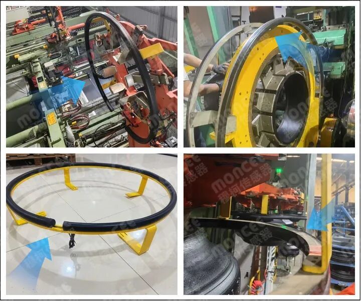
Choosing a Safety Edge Manufacturer for Your Garage Door Project
If you are purchasing Safety Edge for a garage door, industrial door, automatic gate, machine, AGV, or other moving equipment, the best approach is to discuss the complete application with the manufacturer before ordering.
Provide the supplier with:
Door or machine dimensions
Required Safety Edge length
Available mounting space
Cross-sectional requirements
Required bending shape or radius
Cable-exit direction
NO or NC preference
Controller information
Operating environment
Photos or technical drawings of the installation area
Moncee's product range supports multiple profile dimensions, customized lengths, different cable configurations, and different signal modes, making it possible to evaluate the Safety Edge according to the actual mechanical and electrical requirements of the project.
Get a Safety Edge Designed for Your Application
Professional installation starts with correct product selection.
If you are sourcing Safety Edge for garage doors, industrial doors, automated gates, machinery, AGVs, elevators, or OEM equipment, don't purchase solely according to price or appearance. Confirm the profile dimensions, Trigger Distance, Trigger Force, cable configuration, environmental requirements, and controller interface first.
For custom lengths, special bending, OEM projects, or bulk purchasing, providing the manufacturer with your application photos, drawings, dimensions, and wiring requirements can significantly simplify product selection and quotation.
Contact a Safety Edge manufacturer with your installation requirements to receive a suitable profile recommendation, technical configuration, and quotation for your project.



 English
 简体中文
简体中文 Indonesian
 Previous:
 Back to list


