
As AGVs and AMRs move from isolated automation cells into shared factory floors, warehouses, and intralogistics environments, collision avoidance has become a fundamental requirement for mobile robot manufacturers. A robot carrying hundreds of kilograms of material cannot rely solely on mechanical bumpers or basic navigation algorithms. It needs reliable environmental perception that can continuously detect obstacles and provide information to the control system.
This is where AGV / AMR / Mobile Robot Cluster LiDAR becomes commercially important.
However, one distinction should be made before selecting a product: navigation LiDAR, obstacle-avoidance LiDAR, and a certified Safety Laser Scanner are not automatically the same type of device. A laser scanner may provide excellent obstacle detection without being qualified to perform a formally certified safety function.
For OEM manufacturers and system integrators, selecting the right LiDAR therefore requires more than comparing detection range and price. The sensor must be evaluated according to the robot's speed, dimensions, operating environment, detection zones, communication architecture, and deployment scale.
1. Start with the Robot, Not the LiDAR Datasheet
The first mistake in AGV and AMR sensor selection is choosing a LiDAR based on one impressive specification.
A better approach is to define the robot's operating envelope first.
Important parameters include:
Maximum travel speed
Robot dimensions
Payload and maximum load
Forward and reverse movement
Turning radius
Required detection distance
Sensor mounting position
Indoor or outdoor environment
Communication interface
Number of robots in the fleet
For example, an AMR transporting lightweight containers through a controlled warehouse may have very different sensing requirements from a heavy AGV transporting metal components through a production workshop.
The same principle applies to Mobile Robot Cluster LiDAR deployments. When dozens or hundreds of robots are involved, configuration consistency, integration efficiency, and maintenance become almost as important as the sensor's individual detection performance.
2. Understand the Difference Between Navigation LiDAR and Safety Laser Scanner
This distinction is critical for commercial procurement.
A navigation or obstacle-avoidance LiDAR is primarily designed to provide environmental perception. It can detect surrounding objects, generate scan data, support navigation, and trigger obstacle-avoidance logic.
A formally certified Safety Laser Scanner, by contrast, is intended for a safety-related protective function and must be evaluated according to the applicable safety standards and certification requirements.
The distinction is not simply about whether the sensor can “see” an obstacle.
A navigation LiDAR may detect a person and send the information to the robot controller. The controller can then decide to slow down, stop, or change direction.
A safety system requires a much broader evaluation of the complete safety chain, including fault behavior, safety outputs, controller architecture, braking, stopping distance, and applicable performance requirements.
This is why companies should never assume that an industrial LiDAR becomes a certified Safety Laser Scanner simply because it has area detection or obstacle-avoidance functions.
For applications requiring a formally certified safety function, the OEM should request the relevant certification and safety documentation from the supplier before selecting the device.
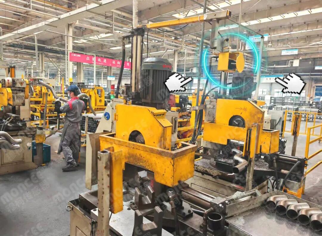
3. Why Scanning Coverage Matters for AGVs and AMRs
A mobile robot operates in a three-dimensional environment, but many AGV and AMR obstacle-detection systems rely on a horizontal scanning plane.
Sensor coverage therefore becomes a major design consideration.
MILS-F30 provides a 270° scanning angle, allowing engineers to monitor a broad area around the sensor. Its default angular resolution is 0.25°, while the documented maximum detection distance reaches 50 m. Under a 10% reflectivity condition, the specified detection distance is 20 m, and measurement accuracy is approximately ±2 cm under the stated conditions.
This combination can be useful for mobile robot environmental perception and obstacle detection.
However, the nominal scanning angle should not be interpreted as complete protection around the vehicle.
Robot geometry, chassis structure, payload overhang, mounting height, turning motion, and blind spots must all be considered.
For bidirectional robots or vehicles operating in tight spaces, engineers may also need to evaluate whether additional sensing positions are necessary.
4. Detection Distance Should Match Vehicle Speed and Stopping Performance
A longer detection range is not automatically better.
The useful detection distance depends on what the robot needs to do after an obstacle is detected.
Consider the following response chain:
Obstacle detection → data transmission → controller processing → control decision → drive response → braking → vehicle stop
The available detection distance must provide enough time for this entire process.
MILS-F30 documentation specifies a minimum network transmission interval of approximately 66 ms in active transmission mode, while the current product reference uses approximately 66 ms for the initial response of area detection.
This parameter should not be interpreted as the complete stopping time of an AGV or AMR.
Actual stopping performance depends on:
Vehicle speed
Vehicle mass
Payload
Drive response
Brake performance
Controller processing
Floor conditions
Detection configuration
For commercial projects, OEM engineers should validate the complete response chain rather than comparing sensor response time alone.
5. Multi-Zone Detection Can Improve Collision-Avoidance Strategies
A mobile robot does not always need to stop immediately whenever an object is detected.
In many applications, it is more effective to establish multiple detection zones corresponding to different response levels.
For example:
Outer Zone → Early Awareness
Detect distant objects and provide information to the navigation or control system.
Middle Zone → Controlled Response
Trigger speed reduction or another predefined response when an object becomes closer.
Inner Zone → Critical Response
Trigger the strongest required control action when an obstacle enters a critical area.
MILS-F30 supports 16 area groups, with three configurable areas per group. The areas can be configured as outer, middle, and inner zones, while supported geometries include rectangles, sectors, and polygons.
This gives OEM engineers greater flexibility when adapting one LiDAR platform to different robot operating modes.
For example, a robot could use one configuration in an open warehouse and another when entering a narrow production aisle.
6. Consider Reflectivity and the Real Industrial Environment
LiDAR performance should always be evaluated against actual application conditions.
Industrial environments may contain:
Dark materials
Highly reflective metal
Pallets
Transparent or semi-transparent objects
Strong sunlight
Dust
Temperature variations
MILS-F30 has an IP65 enclosure rating, an operating temperature range of approximately -25°C to +55°C, and ambient-light resistance up to 80,000 lux. It uses a 905 nm Class 1 laser.
The distinction between maximum range and effective range under specific target conditions is particularly important.
Although the maximum documented detection distance is 50 m, the specified distance for a 10% reflectivity target is 20 m.
Therefore, procurement teams should ask suppliers for application-specific detection performance rather than evaluating only the headline maximum range.
7. Communication Capability Is a Commercial Selection Factor
For an AGV or AMR OEM, the LiDAR is only one component of a much larger system.
The sensor must communicate effectively with the robot controller, navigation computer, or other control devices.
MILS-F30 supports Ethernet and Type-C interfaces for communication and configuration, as well as active and passive data transmission modes.
When evaluating a LiDAR supplier, engineers should therefore ask:
Which communication interfaces are available?
Can detection data be integrated into the existing controller?
Can detection areas be switched according to robot status?
How easy is commissioning?
Can configurations be replicated across multiple robots?
Is technical support available during integration?
These questions become increasingly important as the project moves from a prototype to fleet-scale deployment.
8. Fleet Deployment Changes the Purchasing Decision
A sensor that is easy to configure on one robot may still become expensive to manage across 100 robots.
For AGV / AMR / Mobile Robot Cluster LiDAR, deployment efficiency should therefore be considered during the initial procurement stage.
MILS-F30 supports area configuration import and export, allowing an established configuration to be replicated across units.
For OEM manufacturers, this can help standardize:
Detection-zone configuration
Commissioning procedures
Robot production processes
Replacement-unit setup
Maintenance workflows
The commercial benefit is straightforward: less repetitive engineering work can reduce deployment time and improve consistency across the fleet.
For system integrators, standardized LiDAR configurations can also make it easier to support multiple robots with similar mechanical and operational architectures.
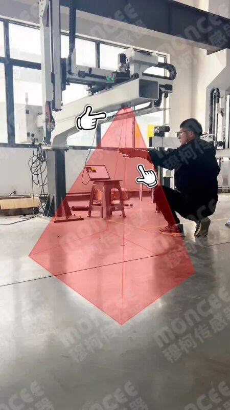
9. Do Not Ignore Mounting and Blind-Spot Design
Even a high-performance LiDAR can produce inadequate protection if it is installed incorrectly.
Engineers should evaluate:
Mounting height
Sensor orientation
Robot chassis obstruction
Payload dimensions
Fork or platform overhang
Turning envelope
Reverse movement
Low-level obstacles
A 2D LiDAR observes its scanning plane. Objects above or below that plane may require additional consideration.
This is particularly important for forklift-style AGVs and robots carrying oversized loads.
Therefore, LiDAR selection and mechanical design should be performed together rather than treating sensor installation as a final-stage engineering task.
10. A Commercial Checklist for AGV and AMR LiDAR Procurement
Before requesting a quotation, OEMs and integrators should prepare a clear technical specification covering:
Requirement | Key Question |
Robot type | AGV, AMR, automated forklift, or another mobile platform? |
Speed | What are normal and maximum speeds? |
Payload | What is the maximum operating load? |
Detection | What distance and coverage are required? |
Zone strategy | One zone or multiple response zones? |
Environment | Indoor, outdoor, dust, sunlight, temperature? |
Interface | Ethernet, I/O, Type-C, or another protocol? |
Installation | Where can the sensor be mounted? |
Fleet size | Prototype, small batch, or large-scale deployment? |
| Safety | Navigation only or a formally certified safety function? |
This information allows suppliers to recommend a suitable architecture rather than simply offering the product with the highest specification.
Conclusion
Selecting a LiDAR for AGV and AMR collision avoidance is ultimately an application-engineering and commercial decision, not simply a sensor specification comparison.
For navigation and obstacle avoidance, an industrial laser scanning sensor such as MILS-F30 can provide broad scanning coverage, configurable detection zones, long-range sensing, communication interfaces, and configuration-replication capabilities suited to industrial mobile robot projects.
At the same time, companies must clearly distinguish an industrial navigation/obstacle-avoidance LiDAR from a formally certified Safety Laser Scanner when the application requires a safety-related protective function.
For OEM manufacturers and system integrators, the better purchasing question is therefore not:
“Which LiDAR has the longest detection range?”
It is:
“Which sensing architecture provides the right combination of detection performance, zone flexibility, integration capability, deployment efficiency, and verified safety performance for our AGV or AMR platform?”
That approach can help companies select sensors that not only work on a prototype, but also remain technically and commercially viable when the project expands into a complete mobile robot fleet.



 English
 简体中文
简体中文 Indonesian
 Previous:
 Back to list


